

When we set out to build the world's first underground farm, the first step was to define the key design criteria that would guide our decision-making process. Once we had defined the problem and started the engineering process, we were met with a series of challenges that kept us on our toes. In this blog post, I hope to present both our design drivers and challenges, as well as key updates from the last few months.
Design Drivers
Here are the four main design drivers on which GreenForges technology is built:
Safety and Hygiene
The farm must ensure the safety of the personnel at all times as well as the hygiene of the plants inside.
Personnel: the farm is designed so that personnel have little interaction with the underground system during planting, harvesting, and in between. This is accomplished by automating the extraction and retraction of the grow modules, requiring only rail-protected on-surface contact.
Food: The farm is designed to ensure the health and hygiene of the plants while minimizing the risk of contamination or infestation. This is accomplished by incorporating food-grade components into all machine components, as well as sanitation and pest-control systems.
Energy Efficiency
The farm must ensure optimal energy efficiency and leverage best-practice principles of circular design.
Light: lighting in the farm consumes a significant amount of energy. As a result, multiple energy-saving elements are incorporated into the design. This includes digitally-assisted LEDs that adjust brightness based on crop growth, as well as reflective surfaces to maximize light penetration. We're also looking into using fiber optics to bring natural sunlight to the farm.
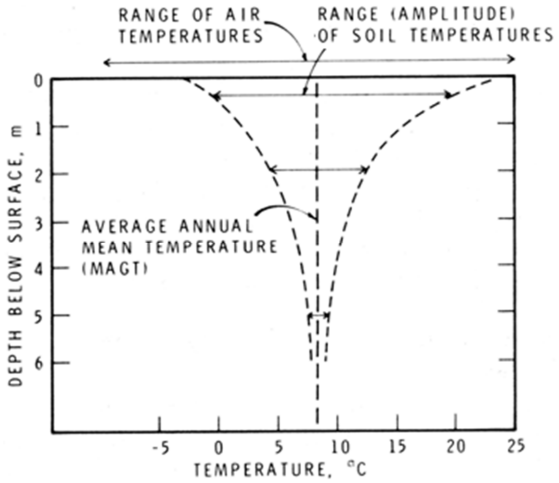
Climatization: The farm uses the soil as a heat sink and an insulator to maintain stable underground temperatures (around 8°C at 6 meters- see Fig.1). This provides cooling and climatization stability, lowering active energy requirements.
Water-Nutrient Feed: The water is continuously collected and recycled in a closed loop system. In addition, the water-nutrient solution will be continuously digitally analyzed to determine the crops' needs and adjust the feed rate accordingly.
Reliability
The farm must demonstrate high reliability, availability, and maintainability.
Fail-safe: The farm is outfitted with multiple fail-safe mechanisms that eliminate the possibility of a one-fail-all-fail scenario. All electromechanical and digital systems are designed with this in mind.
Draining: the farm is equipped with a drain system that circulates water, prevents floods, and removes organic matter from the system.
Maintenance Accessibility: the farm is equipped with easily removable modules as well as a safe climb-down system that allows access in the event of a system failure.
Ease of Use
Farmers must be able to use the farm with ease, and labor time and effort must be reduced.
Automation: by automating climatization, water feed, and plant extraction, the labor effort is kept at a minimum.
Digitization: through digital monitoring systems and a seamless user interface, the farmer can monitor plant growth and health with ease.
Challenges
The design and construction process is not without its challenges; here are the three key areas where we found ourselves designing from the ground up considering the unique application and requirements we have.
Grow Modules
The grow modules are the plants' homes where they spend their time after germination until harvesting. In designing the grow modules, we had to account for an optimal growth environment while streamlining the operational workflow.
Here are three design challenges related to the grow modules:
1. How do we ensure a single module design can accommodate a variety of crops? To do so the design must accommodate:
- Different crop sizes, initially starting with the herbs & leafy greens, while having significant spacial constraints
- Different crop spacings noting the wide range between certain plants (e.g. lettuce requires 18 cm where basil requires 12 cm)
- Seeding and harvesting a variety of crops with ease
2. How do we ensure optimal nutrient-water delivery? To do so the design must:
- Deliver the nutrient solution to the roots and Rockwool in high columns
- Allow the nutrient solution to overcome root entanglement and blockage
- Be watertight and prevents leakage
3. How do we optimize the design for ease of handling and operation? To do so the design must be optimized for:
- Installation
- Extraction
- Harvest
- Cleaning
Where do we stand now?
- We built a small-scale on-surface test system, with 3D printed grow modules. The first column was extracted last week. Despite the lettuce being exposed to unstable conditions while the test system was being set up, the results were much better than expected. Judge for yourself!
(2).jpg)
Extraction Mechanism
The extraction mechanism is a central design piece that enables the operation of underground farming. To be able to grow at such depths and tight space, a simple yet robust mechanism has to be in place. Here are some design challenges related to the extraction mechanism:
- How do we ensure the grow modules are stacked in stable columns without any structural risks during the growth period?
- How do we build a system that is scalable at different depths (50ft, 100ft, 200ft) and different diameters (40", 60", 100")?
- How do we build a system that is safe to be around yet easy to operate?
- How do we build a system that can be operated manually or automated based on the client's needs?
- How do we build a system that has high reliability and requires low maintenance?
- How do we build a system that has low capital and operational costs without compromising quality?
Status: We're currently testing multiple ideas through prototyping and finite element analysis (FEA) simulations.
.jpg)
Climatization Load Estimates
Finally, the climatization loads are a determining factor in the forge's design and profitability analysis. We must define key climatization parameters that comprise the plant recipe in order to keep the plants in an ideal environment. These parameters are: temperature, relative humidity, air velocity, and volumetric airflow. To fully define these parameters, we must first calculate the forge's climatization loads and then perform an optimization analysis until we reach an optimal point between these four parameters. The projected loads listed below have been applied to the Computational Fluid Dynamics (CFD) analysis required to calculate the final loads.
Cooling Load
How much energy is needed for the HVAC Unit to maintain the forge at the desired temperature. The final load would be the net result between the heat sources and heat sinks.
Heat sources: the estimation of the heat generated by the sources below is relatively straightforward as it's obtained from the power values of each component multiplied by the assigned efficiency value. As for the surface temperature, we assumed a fixed room temperature at the surface since the forge will be enclosed by a climatized facility.
- LED Lights
- Electronics Box (sensors, controllers, etc.)
- Fans
- Surface Temperature
Heat sinks: the estimation of the heat sinks is a tricky step that needs to take into account the heat diffusion to the soil at variable depths and soil properties. Considering that soil temperature stabilizes below the six-meter mark, our CFD results show that going underground offers considerable cooling that is reflected in energy savings (estimated at 25%).
- Surrounding Soil
- Hydroponic Solution
Dehumidification Load
How much energy is needed for the HVAC Unit to maintain the forge at the desired relative humidity level. The final load would be the net result between the humidity sources and passive dehumidification.
Humidity sources: estimating the humidity generated through evapotranspiration posed a significant challenge considering the difficulty in measurement. Eventually, we decided to use a common-practice exponential function that estimates the water generated per plant based on the growth day.
- Plant evapotranspiration
Passive Dehumidification: estimating the dehumidification amount from condensation also proved to be a major challenge due to the limited research on estimating the condensation rate in an indoor farm. Nonetheless, using preliminary thermodynamics models in the CFD simulation, the results show a significant amount of humidity (more than 20%) removed from the system due to condensation, again, contributing to further energy savings.
- Condensation on steel casing
Duct Design
Another challenge of going underground is designing the right ducting system to fit in a confined space while ensuring air distribution homogeneity across a 100ft forge. We're studying the use of custom ducts with linear orifices to allow fine control of air velocity at different depths while maximizing homogeneity across the forge.
Status
We're nearing the end of the first phase of CFD simulations required for the climatization load calculation. We'll use the results to size the ducts and HVAC equipment, which will be followed by the second phase of CFD simulation. The second simulation phase includes an optimization analysis for the four previously discussed parameters (temperature, relative humidity, air velocity, and volumetric flow) to determine the optimal operating conditions at various plant growth stages.
.png)
Conclusion
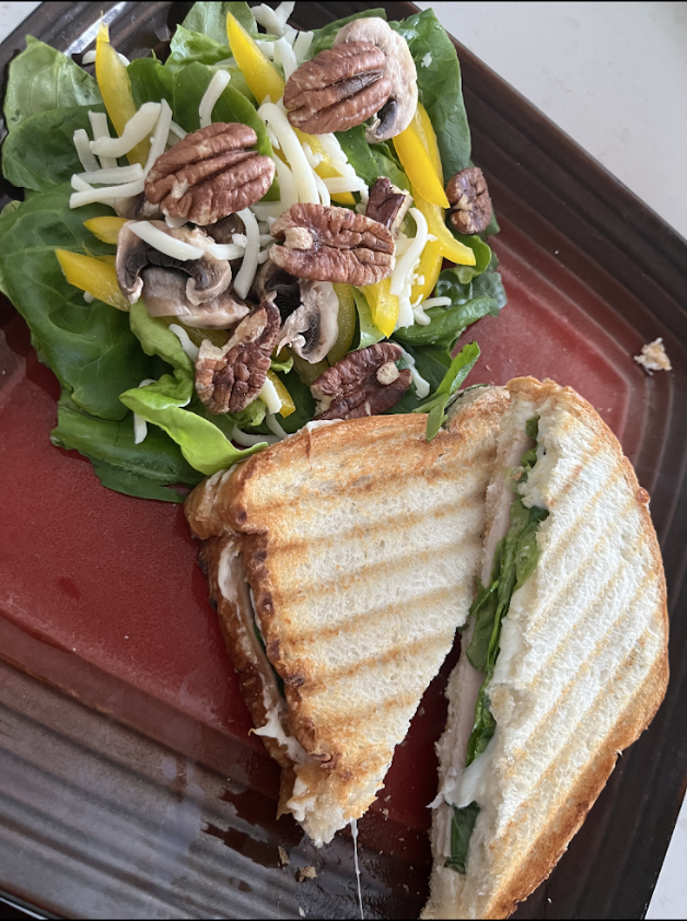
Overall, the road to building an underground farm is paved with technical challenges that require real innovation. On multiple occasions we found ourselves building from scratch and assimilating information from a variety of applications to fit a unique purpose, all while balancing the different layers of the forge between electromechanical, software, and on-surface workflow. So far, the team has made significant progress towards realizing the first forge, with a full-scale pilot planned for before the end of the year. Keep an eye out for more updates, and in the meantime, enjoy this snack made from our first harvest. 🙂
Acknowledgments
This project is fueled by a dedicated and relentless team constantly pushing the boundaries of innovation forward. Special thanks to Andrew Stride, Diego Robitz, Rosalie Gagnon, and Philippe Labrie for the outstanding work on the product development, and the rest of the GreenForges team for staying true to our vision and delivering stellar work day in and day out. Big thank you also to Cameron Thomson for the brilliant renders, our advisor Dr. Mark Lefsrud for the continuous support and mentoring on all things indoor farming, and Mohamed Saghir from Maya HTT for the work on the CFD simulation.